I ask the reader: have you ever dug a hole in the sand on the beach in summer? It all seems straightforward in the beginning, when we use our hand as a digger and remove the first layers of sand. But after several handfuls, when the hole has started to deepen, we can see water creeping in through the sides, flooding our hole. We carry on regardless, lest our neighbours on the next towel to ours were to comment…
When we get elbow deep, the walls start to cave in and fall to the bottom, and the ground we are leaning on gives way. And so we sit before a pretty crater which grows as we remove more sand, our bathing costume full of sand and our sense of shame intact under a hot sun. This is what happens when we dig a tunnel under wet conditions. Can you imagine what it is like to tunnel under the Thames, in London, below sea level?
So, why tunnel under the Thames anyway?
The river Thames is essential for England and for the city of London. It is the most important river, and a source of drinking water. Maritime transport has been making use of it for several millennia, and so it is also an economic driver and source of wealth. But it is also rather dirty.
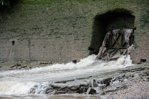
London’s modern sewer system, the same that survived the Great Stink , discharges wastewater into the river when it overflows. We can see this at the Western pumping station (Battersea, below). A dirty Thames is not quite what the Thames should be. A change is needed, and this is coming through the Tideway project.
Source: Tideway
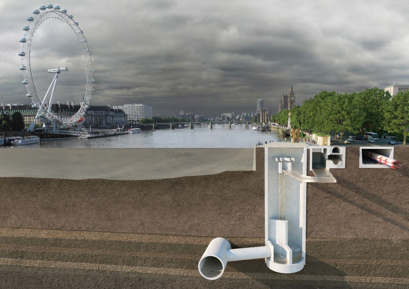
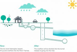
Basically, the project consists of the digging of a huge tunnel under the Thames river bed where it flows past the old locks. Thus, when it rains, rather than overflowing into the river, the water will be diverted into the tunnel. In the cross-section diagram below, the circle below the river bed (right) shows this large overflow.
Source: Tideway
Not all the project is under the Thames, given that not all the old sewer network discharged overflow into the river in the past. The west and east areas are on dry ground, where the soil has a high proportion of rocks and compact materials which are easier to bore. However, tunnelling under the river bed has been a huge technical challenge.
Holding up against ground pressures – literally
Before even talking of the problems caused by the water in this construction project, let’s look at something more tangible: how to overcome existing pressures when digging a hole below ground.
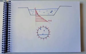
This hand-drawn sketch shows a cross-section of a channel and a horizontal tunnel below it. In red, atmospheric pressure (P0) increases slowly as we go deeper into the water (blue). This is why your ears ring when diving. The greater the depth, the higher the pressure.
Pressure at a point below the earth’s surface depends on the density of the material surrounding it. When we go from water (density ≈1000 kg/m3) to sand (≈1500 kg/m3) or rock (≈2700 kg/m3), the pressure increases dramatically. Again, the deeper we go, the greater the pressure.
The Tideway excavation is carried out at a depth of between 30 and 60 metres, with pressures on the ground increasing as we go downstream and the great overflow progresses. The Tideway cross-section (above, circle) shows how pressures (marked in red) act on all points of the tunnel perimeter.
The tunnel therefore must be reinforced so that its axial strength is not surpassed. To understand the pressures that the tunnel will be subjected to, we can watch the video below, where a watertight tin is taken to a depth of 30 metres below the water surface. Sand, sediment and rocks exert greater pressure!
Tideway Central, and the challenge of digging in wet areas
We started this article with the example of what happens if we dig below the water on a beach: the tunnel soon collapses in on itself. But the pressure at beach level is very low, almost the same as atmospheric pressure. We’ve hardly gone deep enough for axial pressures to collapse the hole, but other forces come into play.
Sand from the walls drops to the bottom. The earth flows, unable to stand up to the side loads, and the top layers of sediment give way due to lack of stability. Everything above the hollowed-out tunnel falls to the bottom. On the beach, with our bucket, it’s not a problem if our architectural underground construction gives way. We simply drop the spade and go for a swim.
But when it comes to the Thames and the surrounding buildings, with civil engineering, safety and human lives at stake, the picture changes completely. We simply cannot allow the ground to give way. The tunnel must stay standing, the walls cannot be allowed to budge.
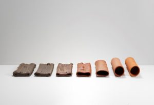
Types of clay found along the 25km of the Tideway project. | Source: Tideway
The tunnel must itself stand up to all the forces acting on it, as well as to ground conditions like humidity, alkalinity and salinity. All the following elements act together at a depth of 30 or 60 metres:
- an extremely high axial pressure, due to the high density of the materials surrounding the tunnel;
- a scarcely compact and wet composition of the soil, which favours both flooding and landslips;
- wet and alkaline soil conditions just below the river (fresh water) which promotes the appearance of chalk and wears down materials;
- wet and salty soil conditions below the tunnel, due to the proximity of sea water, which acts to corrode metals;
- the last two elements additionally give rise to redox reactions, due to differences in potential, which act to wear down materials very quickly.
The part of the project running below the river is where all these adverse forces come into play together. There is hardly any rock to help withstand lateral forces or to act as a water barrier. The tunnelling machines (TBM) excavating the tunnel extract clay, sand, ash and chalk, soft materials which dissolve and act as channels for underground water.
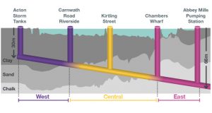
Source: Tideway
This part of Tideway, called Tideway Central, is precisely the section on wich Ferrovial Agroman is working in its joint venture BTL (Bazalgette Tunnel Limited). The most challenging part of the project.
The logistics that makes Tideway Central possible
The tunnel depends on two structures which are indispensable for the project: vertical access shafts and the horizontal tunnel. In other words, a vertical tunnel which is used to lower building materials and the TBMs themselves, and, in the future, to channel excess wastewater; and the great overflow sewer itself, which slopes gently down towards the river mouth.
Construction of cofferdams on the Thames
If civil engineering is not your thing, the word “cofferdams” will mean very little or nothing to you, but they are in fact impressive structures for building in water. The foundations of bridges, the base of dams or the Tideway Central project all require such structures.
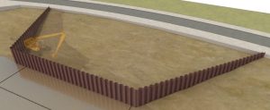
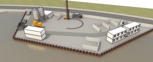
The picture above shows the river channel and its walls (in grey). A trapezium-shaped protecting wall is shown in dark brown on the foreshore, comprised of large metal sheet posts which are sunk into the ground. These form a barrier against water, while the area inside is pumped dry of water and covered with more compact materials. These are brought in on barges.
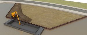
Once the ground has been stabilised, a second wall of sheeting is sunk into the ground, this time making a circle. This second wall is crucial because the ground in the cofferdam is still somewhat wet. Going back to the beach analogy, this would be more or less like placing vertical sheets of metal around our construction. We could dig deeper without the ground caving in, using pumps to pump out the excess water.
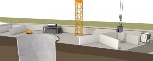
The second circular wall will become the vertical access tunnel, which will initially be used to drop the necessary materials through. In the picture below, you can see how a crane gradually extracts material to reach the required depth. As the tunnel goes deeper, engineers will have to strengthen the shaft against the forces explained previously. Remember: the greater the depth, the higher the pressure.
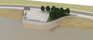
Once construction works are finished, this vertical tunnel will be the overflow collector for wastewater. But this is not the end of the project. Once works are completed, the first retaining wall is removed and the second is covered, leaving a landscaped green area and providing Londoners with an additional park:
Logistics for the horizontal tunnel
Both the cofferdams alongside the Thames and the digging of the tunnel were carried out in a coordinated fashion. In this way, as the TBMs crawled slowly forwards under London, the vertical shafts leading down into the main sewer tunnel could be used to supply the required material.
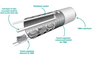
Imagine a TBM like a very slow train (hence the name boring machine!) which gradually puts in place the wall segments which will combat the forces acting on it, water filtration, and soil acidity and alkalinity. Remember, all the issues listed above that a tunnel involves? These tunnel segments are the solution:
Source: Tideway
Ferrovial Agroman had to design a logistics system to coordinate manufacture of each of these wall segments a long way from the site, their transport by barge to the cofferdams, and then lowering through the vertical shafts and along the horizontal tunnel to the TBM cutterhead.
And all of it minutely calculated so that there was never a surplus, but also never the need for the TBM to stop, except for maintenance and repairs. A true work of art in modern engineering which will last for centuries.


There are no comments yet