

This article is the second part of the previous blog: Marine Engineering at the Thames Tideway Tunnel Project (Part I) which talks about the complex renovation works of London’s sewer system, including the existing assets and the type of structures that are being built, both permanent and temporary ones.
Let’s begin by talking about the main tunnel which runns at an average of 40 meters depth below the river bed and that connects the discharges of the existing sewer outfalls at the riverbanks through the permanent structures. In this case, the collected water will be conveyed to the Beckton STW for treatment and then pumped again into the estuary.
The project, known as the Thames Tideway Tunnel is being carried out by joint venture between Ferrovial Construction and Laing O’Rourke (principal contractor of TTT central section, which is located in the heart of London between Fulham and Bermondsey). This section consists of eight independent sites; seven of them which require marine works.
Blackfriars Bridge Foreshore Site (BLABF) is a clear example of the marine engineering achievements made in the project, not only because of the different typologies of marine structures built to enable the construction of the permanent works on the dry but also because of the innovative floating culvert which we explain in this article.
The Floating Culvert
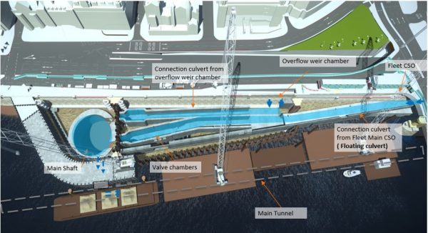
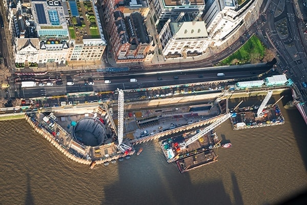
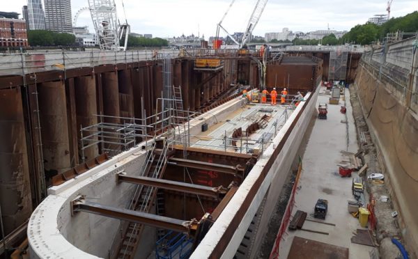
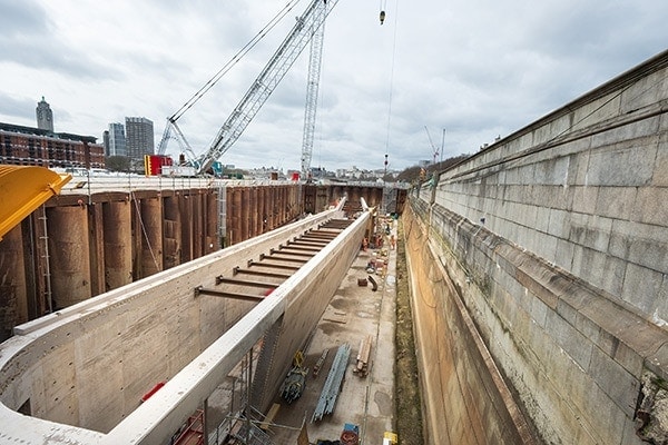
BLABF cofferdam (see image below) is located 100 meters upstream from Blackfriars Bridge, 15 meters away from the Waterloo and City underground line underpass and supported against the existing river wall built 120 years ago in Victorian times.
The sewer outfall to be intercepted by the works is underneath Blackfriars bridge. Due to the underground line, the protected historical assets and the headroom limitations imposed by the bridge deck, it was not possible to continue with the piling works and therefore extend the cofferdam footprint to reach the outfall opening.
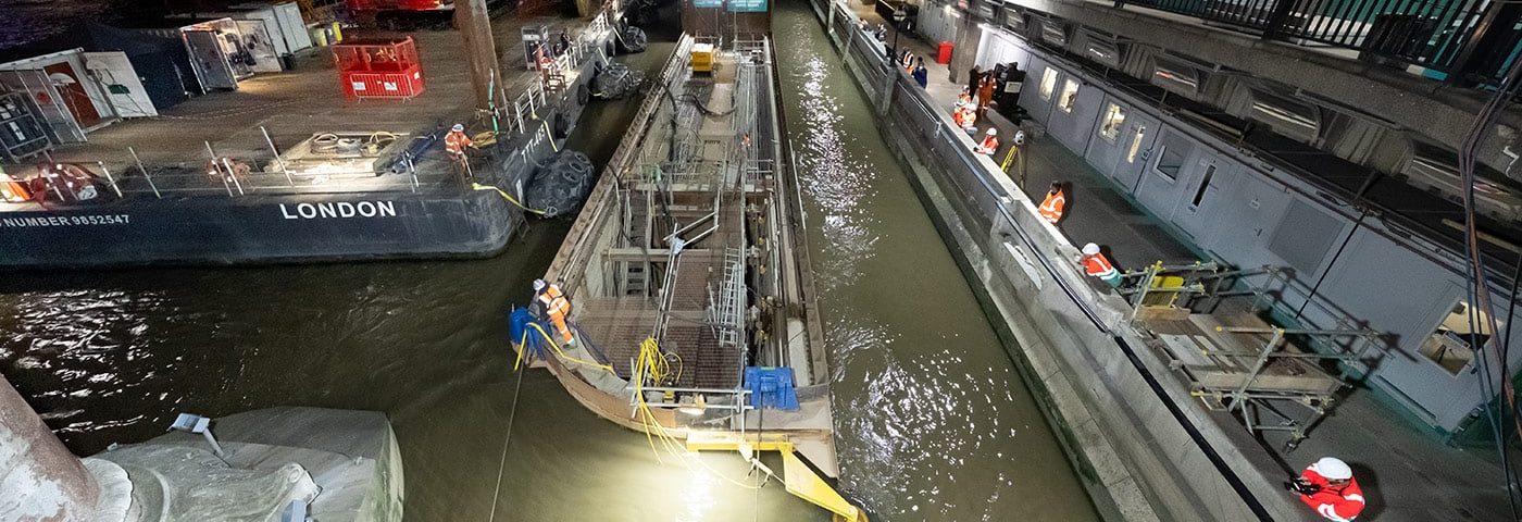
In order to overcome these challenges and restrictions, an innovative engineering solution was proposed: a concrete structure built in the dry and floated to its final position to engage with the existing outfall.
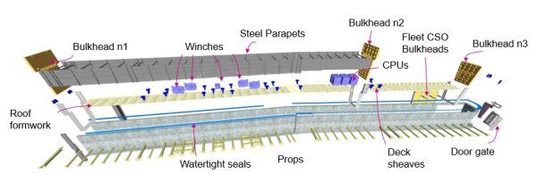
The floating culvert is a reinforced concrete caisson measuring 95 meters in length, with 7 beams and 7 meters supports built using dry construction techniques in the area west of the cofferdam. The 50-meter structure was built in the dry inside the eastern area of the cofferdam and combines a rectangular cross-section and trapezoidal section. Once the structure is in its final position, its purpose is to connect the existing sewer system with the shaft located at the western cofferdam.
The design for the pulling and mooring system was based on traditional methods for floating concrete caissons. The structure was equipped with 4 lines for pulling or braking – two at the stern and two at the bow –connected at one end to winches located in the central area of the caisson and the other to fixed points. The stern lines were anchored to the cofferdam combi wall and the bow lines to the riverbed. Several fairleads were also installed at the top of the structure to guarantee the angles and position of the lines above the culvert deck.
All of these elements and many more, like the fenders that guide the culvert during the flotation operation or the braking structures that help get the final positioning within tolerance, were modeled using BIM technology. A federated 3D model was created to detect and eliminate any potential clash, and also to make easier and effective the coordination of all design interfaces.
Designing with 2D Simulations
The first step in the design of the floating operation was performed using a 2D computer software. By combining the river contours with the current’s velocities, the software provided an initial approximation of the line loads required throughout the operation. However, the asymmetry in both the plan and cross-section difficulted the analysis and introduced some uncertainties.
To verify the results obtained in the 2D simulation, eliminate any uncertainty in the design and represent the 3D effects on the river’s currents, laboratory tests were carried out at the Institute of Environmental Hydraulics at the University of Cantabria (IHCantabria).
A prototype of the culvert in 1:25 scale was also built and equipped with all the ancillary elements that would help complete the real operation. The center of gravity and the inertia of the prototype were also calibrated to increase the similarity between the model and the structure.
In addition, the river basin was modelled using a tank of 20 meters long by 4 meters wide; the river currents and tidal cycles were reproduced accurately with an auxiliary tank and set of pumps. The testing area was also equipped with 20 fans to generate the wind needed, and the wake waves of the river traffic were simulated using a remote-control boat. All existing structures on the river – the cofferdam, existing river wall, and Blackfriars Bridge piles – were modeled, as well.
Three Key Tests
The tests were divided into three phases: in the first one, the results obtained in the 2D simulation were refined. In the second, different potential environmental conditions were simulated, including tidal cycles, current speeds, traffic on the river, and even manual control. Finally, the third phase concluded obtaining the distribution of ideal loads in the pull lines during operation using the lab’s proprietary software.
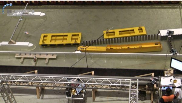
During manual testing, the members of the staff in charge of directing the real operation went to the lab to test the model. In addition to completing the maneuver under normal conditions, accidental situations were also simulated such as losing a pull line during the operation. In all of them, the staff keep the culvert’s prototype under control and completed the operation successfully, demonstrating their experience and increasing exponentially our client’s confidence.
Once the laboratory tests were completed with a positive outcome, the optimal day for the operation was chosen using a tidal assessment carried by the TTT engineering department. The study took in account the tide levels and the current speed recorded on site and the annual tide peak forecasts provided by the Port of London Authority. The study provided the expected tidal curves (level and currents velocity) for each potential date. Finally, by taking other requirements as the minimum required draught into account, 100 possible dates of action were obtained; these were further narrowed down to give the work team a limited set of ideal dates to add to the work schedule.

After reviewing the program in detail, it was decided that the optimal date to carry out the floating operation was early on the morning of August 31, 2020. The operation went smoothly without any unexpected event.
A Team Effort
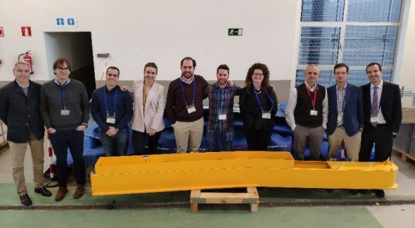
The design of this singular piece of engineering has gone on for almost four years, during this time the construction and engineering team have worked closely together and cooperate with over 10 other companies between engineering consultants and suppliers to achieve this major milestone successfully and on time.
Today, the floating culvert is in its final position, and construction continues to complete the remaining permanent structures.


There are no comments yet